# Unbox and set up your Viam Rover 1
A list of the contents of the Viam Rover 1 kit, instructions for wiring your rover, and links for additional hardware.
> Source: https://docs.viam.com/try/viam-rover/rover-1-setup/
> **Tip:**
>
> A newer version of the Viam Rover, the [Viam Rover 2](https://www.viam.com/resources/rover), replaced the Viam Rover 1.
> If you have a Viam Rover 2, follow [these instructions](/try/viam-rover/setup/) instead.
The Viam Rover 1 shipped preassembled with two encoded motors with suspension, a webcam with a microphone unit, and a 3D accelerometer module.
> **Important:**
>
>
> You must purchase the following hardware separately:
>
> - A Raspberry Pi 4
> - Four 18650 batteries (with charger)
> - A MicroSD card and an adapter/reader
>
This guide covers what's inside the kit, describes each component, provides instructions for wiring your rover, and includes links for additional hardware.
## What's inside the kit
1. One assembled Viam Rover 1.
1. Four M2.5 screws for mounting your Raspberry Pi.
1. Two spare stiffer suspension springs.
You can swap them out with the springs that come with the rover if you need stiffer suspension for higher payload applications.
1. Three different Allen wrenches (1.5 mm, 2 mm, and 2.5 mm) to unscrew the top and mount the Raspberry Pi.
1. Ten female-to-female jumper wires.
All of the wires' colors correspond to the included wiring diagram.
Six are for the motor controller and four are for the accelerometer.
All together, your kit looks like this:
## Rover components
### Dual drive motors with suspension and integrated motor encoders
The motors come with integrated encoders.
For information on encoders, see [Encoder Component](/reference/components/encoder/).
For more information on encoded DC motors, see [Encoded Motors](/reference/components/motor/encoded-motor/).
The kit also includes stiffer suspension springs that you can substitute for the ones on the rover.
Generally, a stiff suspension helps with precise steering control.
In contrast, a soft suspension allows the wheels to move up and down to absorb small bumps on the rover's path.
### Motor driver
The kit comes with an L298N driver dual H-Bridge DC motor driver.
L298 is a high voltage and high current motor drive chip, and H-Bridge is typically used to control the rotating direction and speed of DC motors.
### 720p webcam, with integrated microphone
The webcam that comes with the kit is a standard USB camera device and the rover has a custom camera mount for it.
For more information, see [Camera Component](/reference/components/camera/).
### 3D accelerometer
The [ADXL345](https://github.com/viam-modules/analog-devices/) sensor manufactured by Analog Devices is a digital 3-axis accelerometer that can read acceleration up to ±16g for high-resolution (13-bit) measurements.
You can access it with a SPI (3-wire or 4-wire) or I2C digital interface.
In Viam, you can configure it as a [movement sensor component](/reference/components/movement-sensor/).
### Buck converter
A buck converter is a DC-to-DC power converter and you use it to step down voltage from its input to its output.
The 5A mini560 step-down module has high conversion efficiency and low heat generation.
### Toggle switch
The toggle switch comes wired to the rover and you use it to turn the power on and off.
### Battery pack
The rover comes with a battery holder.
You must purchase four 18650 batteries (and a charger) separately.
The battery holder also has a female jack for an external DC power supply.
#### Four 18650 batteries with a charger
An 18650 battery is a lithium-ion rechargeable battery.
We recommend the button-top type, though either button or flat top can work.
We have used batteries approximately 67.5mm in length, but the battery housing includes a spring to accommodate most batteries of that approximate length.
Any brand is suitable as long as you comply with the battery safety requirements.
Check the [safety](#safety) section for more information.
## Safety
Read all instructions fully before using this product.
This product is not a toy and is not suitable for children under 12.
Switch the rover off when not in use.
> **Warning:**
>
>
> Lithium-ion batteries may pose a flammable hazard.
> This product requires four 18650 lithium-ion batteries.
> Refer to the battery manufacturer's operating instructions to ensure safe operation of the Viam Rover 1.
> Dispose of lithium-ion batteries per manufacturer instructions.
>
> **Caution:**
>
>
> Damage may occur to the Raspberry Pi and/or Viam Rover 1 if wired incorrectly.
> Refer to the manufacturer's instructions for correct wiring.
>
Disclaimer: This product is preliminary and experimental in nature, and is provided "AS IS" without any representation or warranty of any kind.
Viam does not make any promise or warranty that the product will meet your requirements or be error free.
Some states do not allow the exclusion or disclaimer of implied warranties, so the above exclusions may not apply to you.
## Setup
This is the recommended order to assemble your rover:
1. [Install Raspberry Pi OS on the microSD card.](#install-raspberry-pi-os)
2. [Unscrew the top of the rover and screw the Pi to the base.](#attach-the-raspberry-pi-to-the-rover)
3. [Connect the components.](#connect-the-wires)
4. [Screw the top of the rover back on and turn the rover on.](#turn-the-rover-on)
5. [Install `viam-server` and connect to Viam.](#connect-to-viam)
### Install Raspberry Pi OS
Install a 64-bit Raspberry Pi OS onto your Pi following our [Raspberry Pi installation guide](/reference/device-setup/rpi-setup/).
Follow all steps as listed.
You must also enable I2C on your Pi using `sudo raspi-config` so that your Pi can communicate with the accelerometer on your rover.
### Attach the Raspberry Pi to the Rover
Once you have installed Raspberry Pi OS and `viam-server`, put your SD card in the slot on your Pi.
To be able to attach the Raspberry Pi, unscrew the top of the rover with the biggest Allen key.
Then use the smallest Allen key and the provided M2.5 screws to attach the Raspberry Pi to your rover in the designated spots.
The following image shows the four mounting holes for the Pi, circled in red:
> **Tip:**
>
>
> The rover's design allows you to reach the SD card slot at all times, so you can remove or reinsert the SD card without removing the top of the rover.
>
### Connect the wires
> **Tip:**
>
>
> To make it easier for you to see which pin is which, you can print out this [Raspberry Pi Leaf](/appendix/try-viam/viam-raspberry-leaf-8.5x11.pdf) which has labels for the pins and carefully push it onto the pins or fold or cut it so you can hold it up to the Raspberry Pi pins.
> If you use A4 paper, use this [Raspberry Pi Leaf](/appendix/try-viam/viam-raspberry-leaf-A4.pdf) instead.
>
> If you are having trouble punching the pins through, you can pre-punch the pin holes with a pen.
> Only attach the paper when the Pi is unplugged.
> To make attaching the paper easier, use a credit card or a small screwdriver.
>
Wire your Pi to the buck converter, the acceleration tilt module, and the DC motor driver:
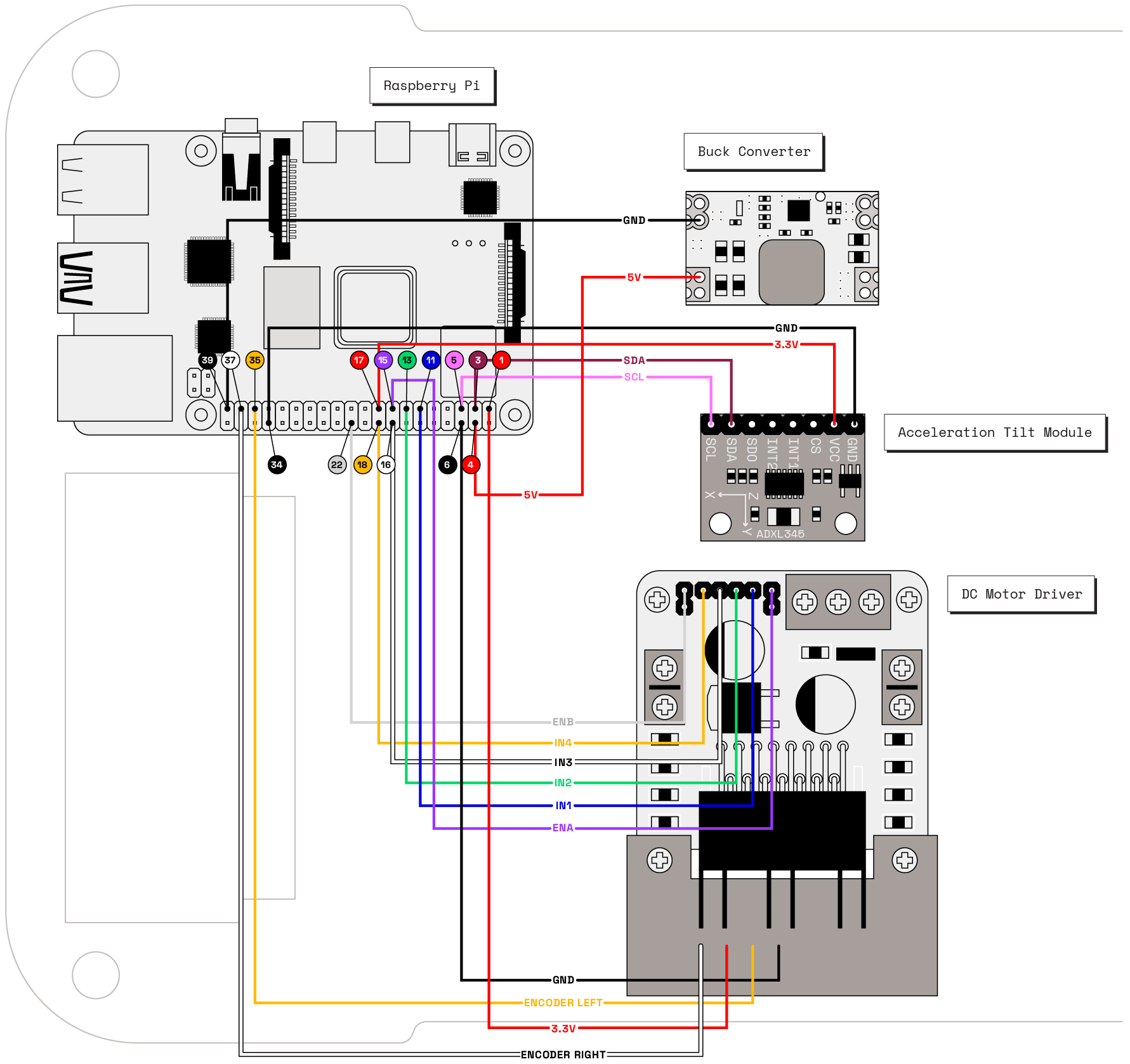
The following pinout corresponds to the diagram:
| Component | Component Pin | Raspberry Pi Pin | Wire Color |
| --------- | --- | ---------------- | ---------- |
| Buck Converter | GND | 39 | black |
| Buck Converter | 5V | 4 | red |
| Acceleration Tilt Module | GND | 34 | black |
| Acceleration Tilt Module | 3.3V power | 17 | red |
| Acceleration Tilt Module | SDA | 3 | maroon |
| Acceleration Tilt Module | SCL | 5 | pink |
| DC Motor Driver | En B | 22 | gray |
| DC Motor Driver | In 4 | 18 | yellow |
| DC Motor Driver | In 3 | 16 | white |
| DC Motor Driver | In 2 | 13 | green |
| DC Motor Driver | In 1 | 11 | blue |
| DC Motor Driver | En A | 15 | purple |
| DC Motor Driver | GND | 6 | black |
| DC Motor Driver | Encoder Left | 35 | yellow |
| DC Motor Driver | 3.3V power | 1 | red |
| DC Motor Driver | Encoder Right | 37 | white |
> **Tip:**
>
>
> En A and En B pins have little plastic jumpers that you need to remove before wiring.
>
> The motor driver on the Viam Rover 1 has 8 pins and 6 wires.
> You must wire it with the outside row pins:
>
>
>
>
>
>
>
>
>
>
>
>
>
>
>
>
>
>
>
>
>
>
Then connect the camera's USB cable to the Pi.
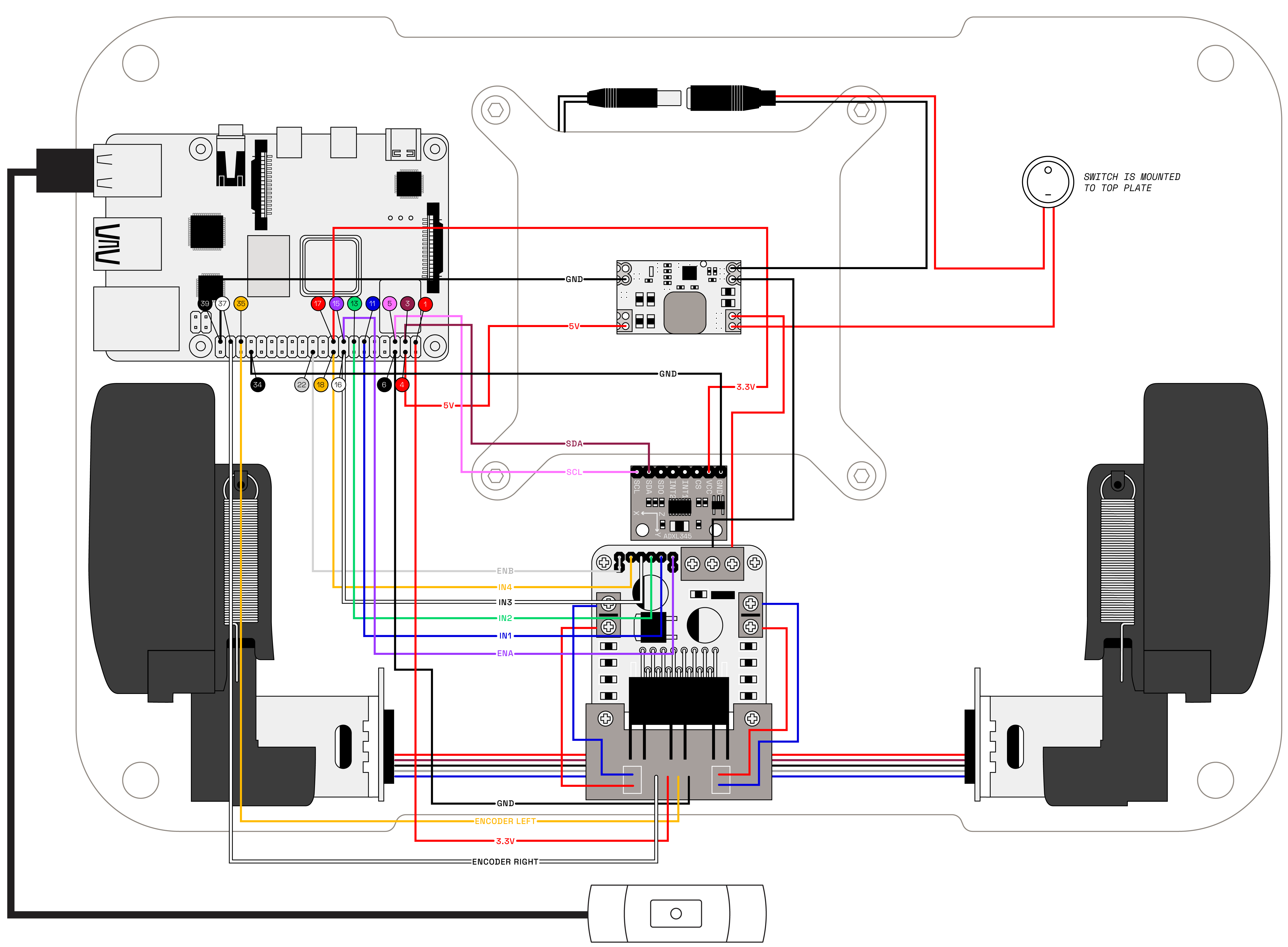
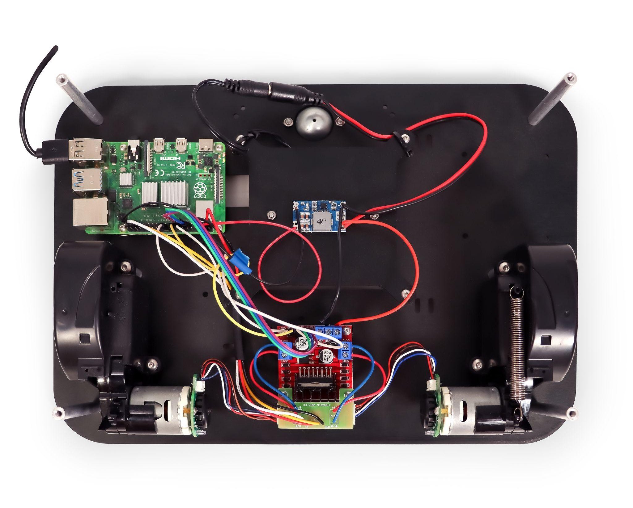
### Turn the rover on
Once you have wired up all the components, reattach the top of the rover and fasten the screws.
Insert the batteries and turn the rover on.
If the Pi has power, the lights on the Raspberry Pi will light up.
### Connect to Viam
While the Pi boots, go to the [Viam](https://app.viam.com/robots) and add a new machine.
Navigate to the **CONFIGURE** tab and find your machine's card.
An alert will be present directing you to **Set up your machine part**.
Click **View setup instructions** to open the setup instructions.
Follow the instructions to install `viam-server` on **Linux / Aarch64**.
`ssh` into your Pi and follow the setup instructions to install and run `viam-server` on the machine.
To configure your rover so you can start driving it, [add the Viam fragment to your Machine](/try/viam-rover/fragments/).
## Next steps
Before you can use your Viam rover with the Viam platform you need to configure your rover:
### Rover build
If you want to learn more about the rover, you can find the CAD files and bill-of-materials (BOM) on [GitHub](https://github.com/viamrobotics/Rover-VR1).
### Extensibility
Due to the aluminum chassis and its expandable mounting features, you can extend the Viam Rover 1.
With it, you can customize your rover by mounting additional sensors, LiDAR, robot arms, or other components.
The following are just a few ideas, but you can expand or modify the rover kit with any components you want:
- For GPS navigation, we support NMEA (using serial and I2C) and RTK.
Make and model don't make a difference as long as you use these protocols.
See [Movement Sensor Component](/reference/components/movement-sensor/) for more information.
- For LiDAR laser range scanning, we recommend RPlidar (including the A1, a sub-$100 LiDAR).
- For robot arms, we tried the [Yahboom DOFBOT robotics arm](https://category.yahboom.net/products/dofbot-jetson_nano) with success.
### Mount an RPlidar to the rover
If you are mounting an RPlidar to your rover, be sure to position the RPlidar so that it faces forward in the direction of travel, facing in the same direction as the included webcam.
For example, if you are using the [RPlidar A1](https://www.slamtec.com/en/Lidar/A1) model, mount it to the Rover so that the pointed end of the RPlidar mount housing points in the direction of the front of the Rover.
This ensures that the generated SLAM map is oriented in the expected direction relative to the Rover, with the top of the generated map corresponding to the direction the RPlidar is facing when you initiate mapping.
If you need a mount plate for your RPlidar A1 or A3 model, you can 3D print an adapter plate using the following:
- [RPlidar A1 adapter STL](https://github.com/viamrobotics/Rover-VR1/blob/master/CAD/RPIidarA1_adapter.STL)
- [RPlidar A3 adapter STL](https://github.com/viamrobotics/Rover-VR1/blob/master/CAD/RPIidarA3_adapter.STL)


 >
>
>
>
>
>