# Build a Robotic Claw Game with a Raspberry Pi
Create your own version of the famous arcade claw machine using a robotic arm and a claw grabber.
> Source: https://docs.viam.com/tutorials/projects/claw-game/
Create your own version of the famous arcade claw machine game using a robotic arm, an arcade claw grabber, and some fun items to pick from.
Fine-tune every intricate detail, from the precision of each grab, to the claw's strength, and even the aesthetics of your control interface.
In this tutorial, you will:
- assemble the claw game machine and learn how to fabricate your own encasement for the machine
- learn how to configure the components using Viam
- master the art of controlling your robot with our [motion service](/reference/services/motion/) using the [Viam Python SDK](https://python.viam.dev/)
- learn how to create a custom control interface using the [Viam TypeScript SDK](https://ts.viam.dev/)
## Requirements
### Hardware
To build your own claw game machine, you need the following hardware:
- A [Raspberry Pi](https://a.co/d/bxEdcAT) with a microSD card, set up following the [Raspberry Pi Setup Guide](/reference/device-setup/rpi-setup/).
- An [xarm6](https://www.ufactory.us/product/ufactory-xarm-6) robotic arm
- An [Arcade claw](https://www.ebay.com/itm/389205760045)
- A [Relay](https://www.amazon.com/gp/product/B095YFJ69T)
- A [24V power supply](https://a.co/d/0iAPD3A4) for the claw
- An iPad or other tablet
- 1 x 4’x4’ fiberboard
- 10 x 2”x4”x8’ lumber
- 4 x 5/16 2 inch lag screws
- A box of 3” deck screws
- 8 x ⅜” 4 inch hex bolts with nuts and washers
- [Velcro cable ties](https://www.amazon.com/Fastening-Adjustable-Organization-Microfiber-Management/dp/B08KH6WTJZ)
- 3 x 4’x2.5’ sheets of plexiglass
- A box of small wood screws for mounting the plexiglass
- Items for the claw to grab.
We used about 600 foam balls for our claw game.
### Software
To build your own claw game machine, you need the following software:
- [`viam-server`](/set-up-a-machine/first-machine/)
- [Python 3](https://www.python.org/download/releases/3.0/)
- [pip](https://pip.pypa.io/en/stable/#)
- [Viam Python SDK](https://python.viam.dev/)
- [Viam TypeScript SDK](https://ts.viam.dev/)
### Tools
You will also need the following tools:
- Drill and drill bit set
- Miter saw or handsaw
- Jigsaw
- Sliding square rule
- Socket wrench set
- Wood glue
- 3D printer
- Clamps
- Tape measure
- Safety glasses and ear protection
## Build the robot
First, assemble the hardware components.
### Build the table
To support the arm and create a surface to hold the prizes, create a flat surface that also has supporting beams so you can securely mount the arm.
You will need to build the table to a size that allows for the arm to reach anywhere on the table surface.
For the xArm6, a table that is 4'x4' works.
1. Cut one 2"x4" in half, creating two 48 inch sides.
1. Then take two 2x4s and cut them to four 46.5 inch lengths.
1. Next, place the 48 inch sides parallel to each other on a flat surface, and place the four other sides perpendicular to and between the 48 inch sides.
1. Attach the 48 inch sides to two of the shorter lengths with deck screws, forming a 4 foot by 4 foot square.
1. Then find the center of the 48 inch sides and mark this on both sides.
1. Measure 2.5 inches from that center mark in either direction, and mark those points as well.
1. These will be the points where we attach the remaining lengths, which will provide a support structure for the robotic arm.
> **Info:**
>
>
> The provided photo does not have the center lengths in the correct location - they are not yet centered or spaced.
>
1. Attach these lengths with deck screws.
1. Use the fiberboard as a tabletop and cut a prize exit hole into it.
Center the exit, make it 10 inches wide, 8 inches long and cut the opening with a jigsaw.
We used two 2 foot by 4 foot fiberboards, but ideally you can use one 4 foot by 4 foot fiberboard.
1. Glue and clamp the tabletop and let it dry overnight.
### Add legs and mount the arm
To finish the table construction, attach the supporting legs and mount the arm to the center of the table.
1. Cut four 2x4s to 78 inches to serve as legs for the cabinet.
1. Measure 30 inches from the top of each and mark this with the sliding square rule.
1. For each leg, line the 30 inch mark up with the top surface of the table, and drill two holes ⅜ inch holes through the leg and table surface.
1. Push two hex bolts through the drilled holes, add washers and nuts, and tighten.
1. For extra stability, cut two more 2x4s to 48 inch lengths, and mount these with deck screws on all four sides of the bottom of the cabinet, bridging the legs.
You can also cut an additional 2x4 and mount it as a fifth leg, going from the center arm supports to the floor.
1. Finally, mount the xArm6 to the top of the table using the lag screws.
Be sure that the lag screws sink into the 2x4 posts below, and that you are mounting the arm so that it is straight, with the X axis facing the player.
You’ll need at least two people to ensure a smooth installation of the arm.
## Configure the robot
Next, configure your newly-built robot.
Add a new machine on [Viam](https://app.viam.com).
On the machine's page, follow the {{< glossary_tooltip term_id="setup" text="setup instructions" >}} to install `viam-server` on the computer you're using for your project.
Wait until your machine has successfully connected to Viam.
Machines are organized into [parts](/reference/glossary/part/)
, where each part represents a computer (a single-board computer, desktop, laptop, or other computer) running `viam-server`, the hardware [components](/reference/glossary/#term-component)
attached to it, and any [services](/reference/glossary/#term-service)
or other resources running on it.
Every machine has a main part which is automatically created when you create the machine.
Since you just created a new machine, your machine's main part is already defined.
Multi-part machines also have one or more sub-parts representing additional computers running `viam-server`.
If you have two computers within the _same machine_, you can use one as the main part and [connect the other to it as a sub-part](/hardware/multi-machine/add-a-sub-part/).
This is the approach this tutorial follows: you'll run the [motion planning service](/reference/services/motion/) on a laptop and connect that laptop as a sub-part to your machine.
> **Tip:**
>
>
> Technically you could configure all the components within one part, but motion planning is more performant when running on a computer like a macOS or Linux laptop running `viam-server`.
>
Use the parts dropdown menu in the top banner of your machine’s page to add a new sub-part called `planning`:
Follow the instructions on the **Setup** tab to install `viam-server` on your development machine and connect to your robot's sub-part.
For more information about parts, see [Machine Architecture: Parts](/hardware/multi-machine/overview/).
Now you are ready to configure the individual components.
Navigate to the **Config** tab of your machine's page and select your main part from the parts dropdown.
### Configure the board
### Builder UI
Click the **Components** subtab.
Click the **Create component** button in the lower-left corner.
Add your [board](/reference/components/board/) with type `board` and model `viam:raspberry-pi:rpi` if you are using a Raspberry Pi 4, Raspberry Pi 3 or Raspberry Pi Zero 2 W.
If you are using a Raspberry Pi 5, use the `pi5` model.
Name your board `myBoard` and click **Add to machine**.
You can name your board whatever you want as long as you use the same name to refer to it in your code.
We named it `myBoard` for simplicity.
This is the only component in the main machine.
Click **Save config** in the lower-left corner of the screen.
### Raw JSON
On the `Raw JSON` tab, replace the configuration with the following JSON configuration for your board:
```json
{
"components": [
{
"model": "pi",
"attributes": {},
"depends_on": [],
"name": "myBoard",
"api": "rdk:component:board"
}
]
}
```
Click **Save config** in the lower-left corner of the screen.
### Configure the arm
Use the parts dropdown menu to navigate to the `planning` sub-part.
### Builder UI
Click the **+** icon next to your machine part in the left-hand menu and select **Blocks**.
Select type `arm`, and model `viam:ufactory:xArm6`.
Name it `myArm` and click **Add to machine**.
Configure the arm component with the arm’s IP address in the `host` field.
Our arm’s address was `10.1.1.26`, but you should use the IP address for your arm.
For more information on xArm6 configuration, see [Configure an xArm6 Arm](https://github.com/viam-modules/viam-ufactory-xarm).
Click **Save config** in the lower-left corner of the screen.
### Raw JSON
On the `Raw JSON` tab, replace the configuration with the following JSON configuration for your arm:
```json
{
"components": [
{
"model": "viam:ufactory:xArm6",
"api": "rdk:component:arm",
"attributes": {
"acceleration_degs_per_sec_per_sec": 0,
"host": "10.1.1.26",
"speed_degs_per_sec": 0
},
"depends_on": [],
"frame": {
"parent": "world",
"translation": {
"x": 0,
"y": 0,
"z": 0
},
"orientation": {
"type": "ov_degrees",
"value": {
"th": 0,
"x": 0,
"y": 0,
"z": 1
}
}
},
"name": "myArm"
}
]
}
```
Click **Save config** in the bottom left corner of the screen.
### Configure the gripper
### Builder UI
Click **Create component** and add your [gripper](/reference/components/gripper/).
Choose type `gripper` and model `fake`.
Name it `gripper` and click **Add to machine**.
Set up a `fake` model.
You will only use this as a placeholder for the size of the gripper to use with Viam’s [frame system](/operate/reference/services/frame-system/)
later.
Measure the claw’s height and width, and enter these values for the `fake` model.
Ours was 120mm for the width and 180mm for the height.
Click **Save config** in the lower-left corner of the screen.
### Raw JSON
On the `Raw JSON` tab, replace the configuration with the following JSON configuration for your arm and gripper:
```json
{
"components": [
{
"model": "xArm6",
"api": "rdk:component:arm",
"attributes": {
"acceleration_degs_per_sec_per_sec": 0,
"host": "10.1.1.26",
"speed_degs_per_sec": 0
},
"depends_on": [],
"frame": {
"parent": "world",
"translation": {
"x": 0,
"y": 0,
"z": 0
},
"orientation": {
"type": "ov_degrees",
"value": {
"th": 0,
"x": 0,
"y": 0,
"z": 1
}
}
},
"name": "myArm"
},
{
"frame": {
"translation": {
"y": 0,
"z": 0,
"x": 0
},
"orientation": {
"type": "ov_degrees",
"value": {
"z": 1,
"th": 0,
"x": 0,
"y": 0
}
},
"geometry": {
"r": 120,
"translation": {
"z": 180,
"x": 0,
"y": 0
}
},
"parent": "myArm"
},
"name": "gripper",
"model": "fake",
"api": "rdk:component:gripper",
"attributes": {},
"depends_on": []
}
]
}
```
Click **Save config** in the bottom left corner of the screen.
## Set up the claw
### 3D print the claw mount
[Download the STL](https://github.com/viam-labs/claw-game/blob/main/xarm6ClawMount.stl) for the claw mount, and use a 3D printer to print the mount for in between the claw and the xArm6.
### Attach the claw to the printed mount
1. With a screwdriver, remove the metal top cap from the claw by removing the side screws.
1. Remove the string that came with the claw, it is not needed.
1. Extend 2 or 3 M3 button socket cap screws through the recessed inner holes of the printed mount and through the slots on the top of the claw cap.
1. Secure the M3 screws with nuts and tighten.
1. Attach the printed mount and claw end cap to the claw, add the previously removed screws and tighten.
### Mount the claw to the arm
1. Using two M20 screws, attach the printed mount to the end of the arm and tighten.
1. Using hook-and-loop cable ties, run the claw’s cable along each segment of the arm to the arm base, making sure the cord is secure but with some slack to allow for movement.
### Wire and test the claw
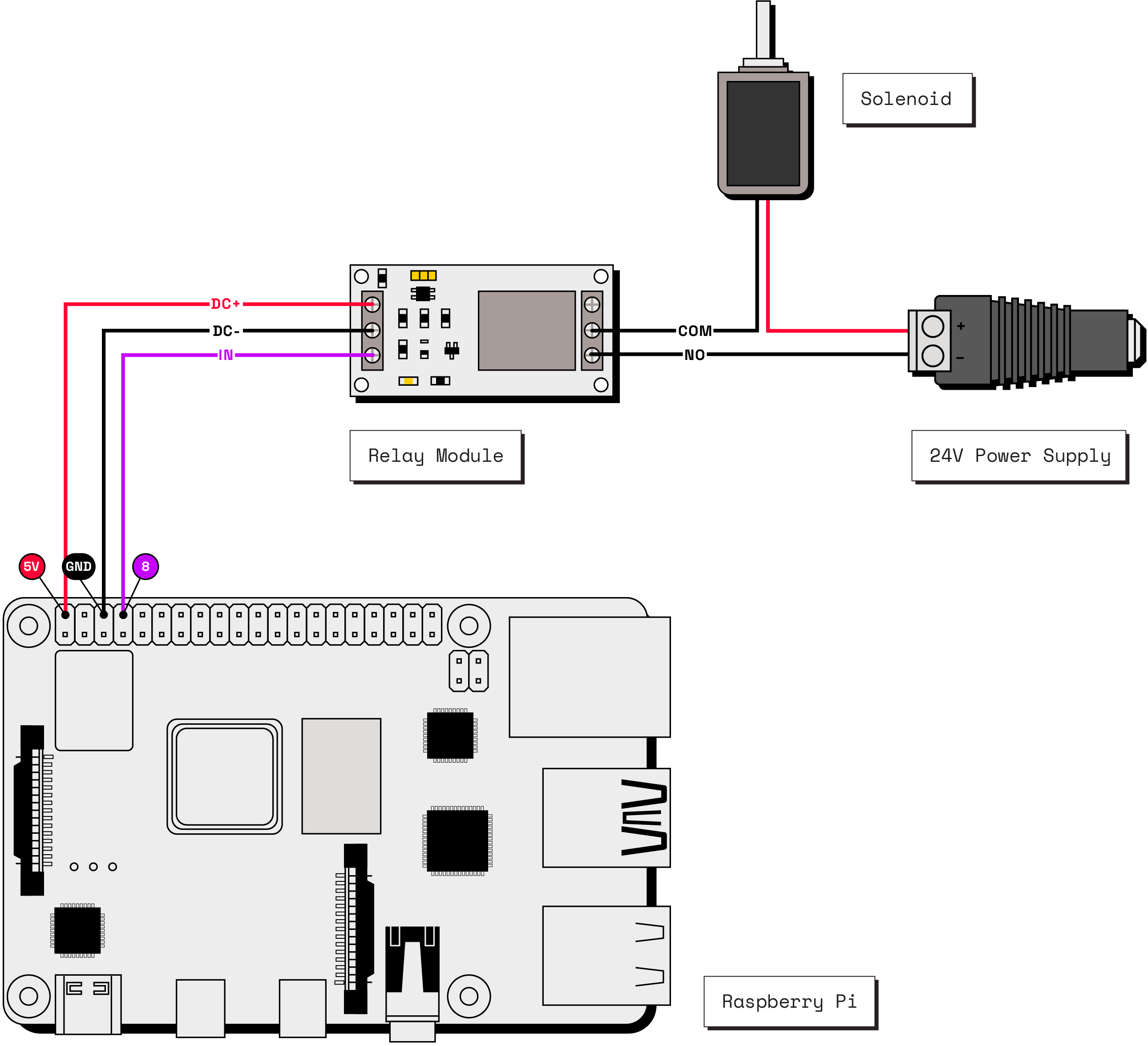
The arcade claw is actuated when a solenoid is powered, acting as a magnet to pull the claw shut.
For this project, we use a relay, which allows us to programmatically control when power flows to the claw’s solenoid.
1. Using a barrel jack adapter, connect the positive (red) wire from the claw to the positive terminal of the adapter.
1. Then, connect the negative (black) wire from the claw to the `COM` terminal on the relay.
1. Cut a length of wire and connect it between the `NO` terminal on the relay and the negative terminal on the barrel jack adapter.
This creates a _normally open_ circuit, which means the circuit is normally not complete and the claw is therefore normally not powered.
In order to control the claw through Viam, you will now wire the relay to the Raspberry Pi.
1. First, power down the Pi.
Then take three female jumper wires, cut off one end of each, and strip the ends.
1. Use one wire to connect the `DC+` terminal on the relay to pin 2 (`5v`) on the Pi.
1. Use the second wire to connect the `DC-` terminal on the relay to pin 6 (`ground`) on the Pi.
1. Use the third wire to connect the `IN` terminal on the relay to pin 8 (`GPIO`) on the Pi.
1. Now power on the Pi and plug the 24V DC adapter into the wall and the barrel jack adapter.
Once `viam-server` has started, you can test closing and opening the claw.
The Viam `board` component gives us an interface for this.
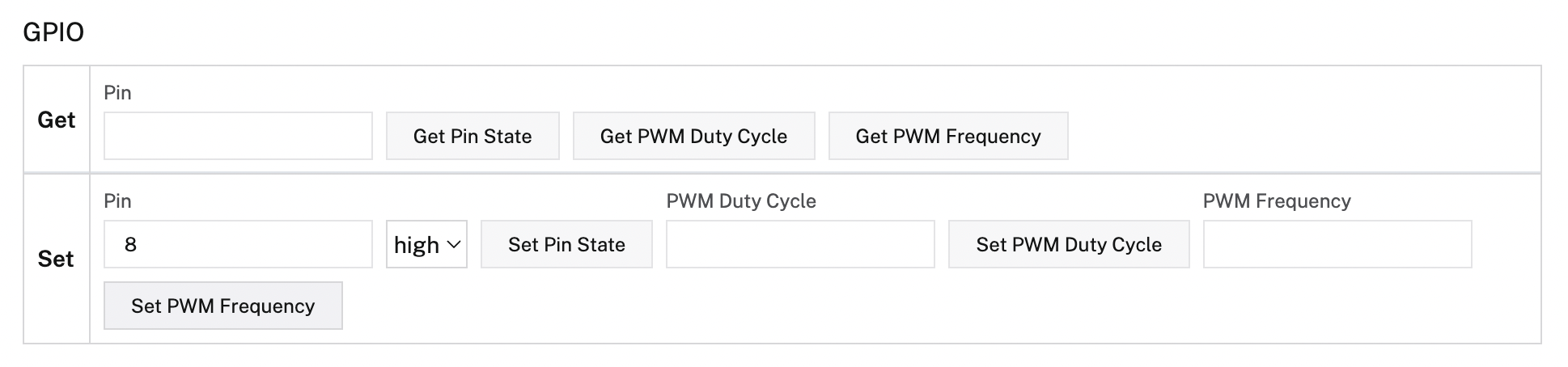
Go to the **Control** tab for your machine, open the `MyBoard` card, enter `8` next to **Set** under the GPIO interface, choose `high` and click **Set Pin State**.
The relay will trigger the claw circuit to be closed when the GPIO pin state is set to high and your claw will close.
Now select `low` and click **Set Pin State** again: the claw will open.
## Create obstacles and a world state
The claw game machine will use the [motion service](/reference/services/motion/) to plan its movements.
To make sure the arm doesn't hit the walls of the enclosure or the prize drop hole, you need to create representations of obstacles around the arm that the motion service can use when planning.
Obstacles are geometries located at a pose relative to some frame.
When solving a motion plan with movable frames that contain inherent geometries, for example parts of the arm, the solved path is constrained such that none of those inherent geometries intersect with the obstacles.
You can pass information about the robot’s environment, including obstacles, to the Viam platform through a data structure named [WorldState](https://python.viam.dev/autoapi/viam/proto/common/index.html#viam.proto.common.WorldState).
These obstacle representations are defined in a JSON. You can find the file we used in our [claw game repository](https://github.com/viam-labs/claw-game/blob/main/obstacles.json).
Represented in that file are obstacles for the prize drop hole, and each of the four walls based on measurements we took from our enclosure.
If the dimensions of your enclosure differ from ours, adjust your `obstacles.json` file to match your enclosure.
The obstacles for our arm are configured in reference to the "world" frame which is defined as a , which is a special frame that represents the starting point for all other frames in the robot's world.
The list of obstacles are defined in a `WorldState` object, which is passed as an argument in each [move()](/reference/apis/services/motion/#move) call.
> **Tip:**
>
>
> If the arm is not mounted exactly perpendicular to the x/y axis of the enclosure, you can adjust the theta (_th_) of the arm within the arm component configuration by a number of degrees to compensate.
> Obstacles can then be configured as if the arm were straight in the enclosure.
> See the [frame system documentation](/motion-planning/frame-system/overview/) for more information.
>
### Find the home pose within the enclosure
By moving the arm through the **Control** tab, you can determine the arm's ideal home pose, which is the position the arm starts each game and the one it returns to after making a grab.
You can also determine the desired distance between the lateral plane and the pick up level, which is how you determine how far to drop the grabber.
If your enclosure is sufficiently different from ours, these values may be different: it's best to test your own measurements by moving your arm around your enclosure from the **Control** tab.
For our enclosure, the hole pose and dimensions are as follows:
```sh {class="command-line" data-prompt="$"}
hole_origin = Pose(x=470, y=125, z=0, o_x=0, o_y=0, o_z=1, theta=15)
hole_dims = Vector3(x=250, y=400, z=300)
```
Additionally, the home position origin and dimensions where the arm needs to be in order to drop the prize are as follows:
```sh {class="command-line" data-prompt="$"}
home_pose = Pose(x=390.0, y=105.0, z=500.0, o_x=0, o_y=0, o_z=-1, theta=0)
home_pose_in_frame = PoseInFrame(reference_frame="world", pose=home_pose)
```
The floor level where the claw drops has different numbers for `x` and `y` since you can pick items from anywhere on the plane, but the Z axis is always the same since you always drop to the same level.
We tested between `240` and `280` for this level, but you can adjust it to your liking.
## Use Python code to control the arm
Use `git` to clone the [Claw Game project repository](https://github.com/viam-labs/claw-game/):
```sh {class="command-line" data-prompt="$"}
git clone https://github.com/viam-labs/claw-game
```
The claw game repository includes the Python test script [`CLI-test.py`](https://github.com/viam-labs/claw-game/blob/main/CLI-test.py), which connects to your robot, creates an orientation constraint so the last arm joint is always facing down, and provides functions to:
- Grab and release the claw
- Move the arm to the home position
- Move the arm to a test position
- Move the arm forward, backward, right, and left
- Move the arm to the drop position
- Move the arm to the up position
This script provides an interface to run a single move command, or to run move commands in sequences.
You can adjust the code to your liking.
In the following, you can read about what the different sections of the code do.
First, the code imports the required packages:
```python {class="line-numbers linkable-line-numbers"}
import asyncio
import argparse
import json
from viam.robot.client import RobotClient
from viam.rpc.dial import Credentials, DialOptions
from viam.components.board import Board
from viam.components.arm import Arm
from viam.services.motion import MotionClient
from viam.proto.common import Pose, PoseInFrame, Vector3, Geometry, \
GeometriesInFrame, RectangularPrism, WorldState
from viam.proto.service.motion import Constraints, LinearConstraint, \
OrientationConstraint
```
Then it creates an argument parser, defining required and optional arguments to create a user-friendly command line interface:
```python {class="line-numbers linkable-line-numbers"}
parser = argparse.ArgumentParser()
parser.add_argument('--command', type=str, required=True)
parser.add_argument('--sequence', type=str, required=False)
parser.add_argument('--location', type=str, required=True)
parser.add_argument('--password', type=str, required=True)
args = parser.parse_args()
```
Next, it creates some constants to define how much the arm should move at each call, where the home position should be and where it should drop to grab the prizes.
You can tweak these numbers as needed.
```python {class="line-numbers linkable-line-numbers"}
# The amount to move in mm for each command forward, backward, left, right
move_increment = 50
# Define home position to return to
home_plane = 500.0
home_pose = Pose(x=390.0, y=105.0, z=home_plane, o_x=0, o_y=0, o_z=-1, theta=0)
# Define plane to grab on
grab_plane = 240.0
```
Then we define the [constraints](https://python.viam.dev/autoapi/viam/proto/service/motion/index.html#viam.proto.service.motion.Constraints) - in this case we are using an [orientation constraint](/reference/services/motion/constraints/#orientation-constraint).
The orientation constraint places a restriction on the orientation change during a motion, as the arm in a claw game should always face down so the gripper is always in a position where is can descend and grab a prize:
```python
constraints = Constraints(orientation_constraint=[OrientationConstraint()])
```
Next the code imports the obstacles.json file and defines the `world_state` representing the robot's physical environment:
```python {class="line-numbers linkable-line-numbers"}
def get_world_state():
with open('obstacles.json', 'r') as f:
geometries = json.load(f)
world_state_obstacles = []
for geometry in geometries:
center = geometry['translation']
orientation = geometry['orientation']['value']
center = Pose(
x=center['x'],
y=center['y'],
z=center['z'],
o_x=orientation['x'],
o_y=orientation['y'],
o_z=orientation['z'],
theta=orientation['th'],
)
dims = Vector3(x=geometry['x'], y=geometry['y'], z=geometry['z'])
world_state_obstacles.append(
Geometry(center=center,
box=RectangularPrism(dims_mm=dims),
label=geometry['label']))
obstacles_in_frame = GeometriesInFrame(reference_frame="world",
geometries=world_state_obstacles)
return WorldState(obstacles=[obstacles_in_frame])
world_state = get_world_state()
```
Next, the code defines a grab function to use GPIO to open and close the gripper by setting the Raspberry Pi pin state to `true` or `false`:
```python {class="line-numbers linkable-line-numbers"}
async def grab(board, doGrab):
# Note that the pin supplied is a placeholder. Please change this to a
# valid pin you are using.
pin = await board.gpio_pin_by_name('8')
if doGrab:
# opens the gripper/release
await pin.set(True)
else:
# closes the gripper/grab
await pin.set(False)
```
Lastly, the code defines the functions `move_absolute()`, `home()`, `move_to_offset()` and `move_z()`, which construct new pose requests to send to the [motion service](/reference/services/motion/).
```python {class="line-numbers linkable-line-numbers"}
async def move_absolute(arm, motion_service, pose):
destination = PoseInFrame(reference_frame="world", pose=pose)
await motion_service.move(component_name=arm,
destination=destination,
world_state=world_state,
constraints=constraints)
async def home(arm, motion_service):
# Makes sure to first move the arm up in z axis
await move_z(arm, motion_service, 500)
# Generate a sample "home" pose around the drop hole and demonstrate motion
home_pose_in_frame = PoseInFrame(reference_frame="world", pose=home_pose)
await motion_service.move(component_name=arm,
destination=home_pose_in_frame,
world_state=world_state,
constraints=constraints)
async def move_to_offset(arm, motion_service, offset):
# Get current position of the arm
current_position = await motion_service.get_pose(
component_name=arm,
destination_frame="",
supplemental_transforms=None)
print('current position: ', current_position)
# Calculate new pose to move the arm to
pose = Pose(
x=current_position.pose.x + offset.x,
y=current_position.pose.y + offset.y,
z=current_position.pose.z + offset.z,
o_x=0,
o_y=0,
o_z=-1, # negative z means claw will point down
theta=0
)
print('moving to position: ', pose)
# Move arm
destination = PoseInFrame(reference_frame="world", pose=pose)
await motion_service.move(component_name=arm,
destination=destination,
world_state=world_state,
constraints=constraints)
async def move_z(arm, motion_service, z):
# Get current position of the arm
current_position = await motion_service.get_pose(
component_name=arm,
destination_frame="",
supplemental_transforms=None)
print('current_position: ', current_position)
# Construct new pose to get to desired z position
pose = Pose(
x=current_position.pose.x,
y=current_position.pose.y,
z=z,
o_x=0,
o_y=0,
o_z=-1, # negative z means claw will point down
theta=0
)
print('moving to position: ', pose)
# Move arm
destination = PoseInFrame(reference_frame="world", pose=pose)
await motion_service.move(component_name=arm,
destination=destination,
world_state=world_state,
constraints=constraints)
```
The `main()` function initializes different resources and then handles command line arguments to move the arm in a sequence for testing and debugging:
```python
async def main():
robot = await connect()
print('Resources:')
print(robot.resource_names)
# Pose using motion service, grabbing the service from local computer
motion_service = MotionClient.from_robot(robot, "planning:builtin")
# myBoard
my_board = Board.from_robot(robot, "myBoard")
# my arm name
my_arm_resource = "myArm"
print("arm resource", my_arm_resource)
commands = [args.command]
if args.command == "sequence":
commands = args.sequence.split(",")
for command in commands:
if command == "drop":
print("will drop")
# Moves the arm's z position to grab plane
await move_z(my_arm_resource, motion_service, grab_plane)
if command == "up":
print("will go up")
# Moves the arm's z position to home plane
await move_z(my_arm_resource, motion_service, home_plane)
if command == "home":
print("will return home")
# Goes to home position
await home(my_arm_resource, motion_service)
if command == "left":
print("will move left")
# Moves the arm's y position to left
await move_to_offset(my_arm_resource,
motion_service,
Vector3(x=0, y=-move_increment, z=0))
if command == "right":
print("will move right")
# Moves the arm's y position to right
await move_to_offset(my_arm_resource,
motion_service,
Vector3(x=0, y=move_increment, z=0))
if command == "forward":
print("will move forward")
# Moves the arm's x position to forward
await move_to_offset(my_arm_resource,
motion_service,
Vector3(x=move_increment, y=0, z=0))
if command == "backward":
print("will move backward")
# Moves the arm's x position to backwards
await move_to_offset(my_arm_resource,
motion_service,
Vector3(x=-move_increment, y=0, z=0))
if command == "grab":
print("will grab")
# Closes the gripper
await grab(my_board, True)
if command == "release":
print("will release")
# Opens the gripper
await grab(my_board, False)
if command == "sleep":
print("will sleep one second")
await asyncio.sleep(1)
if command == "test":
print("""will move to the test position, drop, grab, return home
and release""")
await move_absolute(
my_arm_resource,
motion_service,
Pose(x=0.0, y=380, z=home_plane, o_x=0, o_y=0, o_z=-1, theta=0)
)
await move_z(my_arm_resource, motion_service, grab_plane)
await grab(my_board, True)
await home(my_arm_resource, motion_service)
await grab(my_board, False)
# Don't forget to close the robot when you're done!
await robot.close()
if __name__ == '__main__':
asyncio.run(main())
```
Use `CLI-test.py` to run these commands from the command line, for example:
```sh {class="command-line" data-prompt="$"}
python3 CLI-test.py --password mypass --location mylocation --command grab
```
Or, you can run sequences of these commands together, for example:
```sh {class="command-line" data-prompt="$"}
python3 CLI-test.py --password mypass --location mylocation --command sequence \
--sequence grab,sleep,release,sleep,grab,sleep,release
```
Now that the arm is set up and you have a CLI script you can use for testing - try testing the motion and claw grab with different items.
Consider that the size, weight, and shape of the item being grabbed will affect the claw's ability to successfully grab it.
You can also try increasing the voltage of the claw's power supply if you feel like it is struggling to pick up objects, especially if the objects are heavy (but don’t exceed the limits of the relay).
We tested with different Viam swag items such as t-shirts and hats, but found that foam balls worked the best for us.
## Add the sides and fill the enclosure with prizes
In order to house the prizes, you’ll need to enclose three of the sides (front, left, and right sides) of the upper cabinet with plexiglass.
1. Have someone hold the plexiglass in place while you carefully pre-drill holes for the wood screws.
1. Carefully screw the wood screws in place, being sure not to tighten excessively, as this can crack the plexiglass.
1. Add a short barrier in the back to stop the prizes from falling out.
We used the remaining 2x4 section for this.
1. Then, do the same for the prize exit hole.
We used some extra fiberboard and glue, but you could use cardboard, wood, or any other rigid material available.
Now you can fill the enclosure with prizes!
Fill the enclosure generously, but make sure that the prizes don’t overflow from the prize exit hole or the backstop.
We ended up using over 600 foam balls.
## Create a custom interface using TypeScript
Now that you've built out and tested all of the main functionality of your claw game, it's time to design a custom interface to control it.
This tutorial shows you how to create the interfaces for a touch screen tablet (in our project, we mounted an iPad to the facade of our claw machine prototype).
The interface is hosted on a separate macOS or Linux computer locally and then accessed on the tablet using your computer's local address.
Within the project code repository, the src folder contains the main TypeScript code that executes all robot commands.
The `static` folder contains the frontend code, including styling and HTML.
To use the [Viam TypeScript SDK](https://ts.viam.dev/) you must install the dependencies in your main project folder.
1. Make sure you have the latest version of [Node.JS](https://nodejs.org/en) installed.
1. Once you have installed Node, you can now fetch all dependencies, including the Viam TypeScript SDK, by running the following command in your project directory:
```sh {class="command-line" data-prompt="$"}
npm install
```
1. Determine your machine's location secret and host address by navigating to the **CONNECT** tab.
Use the host address of your main machine part, as it will reference all parts of your machine.
To show your machine's API key in the sample code, toggle **Include API key**.
{{< alert title="Caution: Keep your API key safe" color="caution" >}}
We strongly recommend that you add your API key as an environment variable.
Anyone with your API key can access your machine, and the computer running your machine.
{{< /alert >}}
1. Then, run the following command to start the custom TypeScript interface, inserting your machine's API key as the argument for `VIAM_API_KEY`,your machine's API key ID as the argument for `VIAM_API_KEY_ID`, and your main part host address for `VIAM_LOCATION`:
```sh {class="command-line" data-prompt="$"}
export VIAM_LOCATION=;VIAM_API_KEY=;VIAM_API_KEY_ID=;npm run start-simple
```
> **Info:**
>
>
> Providing these values in this fashion ensures that your security keys are not accessible to others when publishing your code.
>
1. Visit `localhost:8000` in a browser.
Press the buttons to execute the control commands defined in **main.ts** and watch your robot arm move around using the simple user interface.
The TypeScript app reads in the obstacles defined in the same `obstacles.json` JSON file that you used with the Python testing script, and creates a world state.
The TypeScript interface code includes functions that define movements in each direction on a plane relative to the base of the game.
This includes forward, back, left, right, and home functions.
If you look through the code you will notice each of these functions follow the same convention by using the Motion Client method [`move()`](https://ts.viam.dev/interfaces/Motion.html#move) and passing in all of the obstacles defined globally as well as the [`WorldState`](https://ts.viam.dev/classes/commonApi.WorldState.html) in each function:
```js {class="line-numbers linkable-line-numbers" data-line="25"}
async function right(motionClient: MotionClient, armClient: ArmClient) {
if (ignoreInterrupts && await armClient.isMoving()) { return }
// Get current position of the arm
console.log('im trying to print the current position')
let currentPosition = await motionClient.getPose(myArm, 'world', [])
console.log('current position:' + JSON.stringify(currentPosition))
// Define the new right position by adding to the y value incrementally so that your robot arm will move
let rightPose: Pose = {
x: currentPosition.pose!.x,
y: currentPosition.pose!.y + moveDistance,
z: currentPosition.pose!.z,
theta: 0,
oX: 0,
oY: 0,
oZ: -1
};
let rightPoseInFrame: SDK.PoseInFrame ={
referenceFrame: "world",
pose: rightPose
}
// Call the move method with the new rightPose values to move your arm and pass in your machine component name, WorldState, and constraints
await motionClient.move(rightPoseInFrame, myArm, myWorldState, constraints)
}
```
For each function that moves the arm in the Python script, the front end has corresponding buttons that trigger these actions in your browser environment.
Each of these button functions is initialized the same way for each corresponding function.
For example, the following code handles movement to the right:
```js {class="line-numbers linkable-line-numbers"}
// Creating a button function that corresponds to the HTML element that will show on your webpage
function rightbutton() {
return document.getElementById('right-button');
}
// Since we are designing for a touch screen, we are using a touchstart event for our button command
rightbutton().ontouchstart = async () => {
rightHandler()
};
// This function is where the move function is called as well as adding some
// timeout and color changing media queries
async function rightHandler() {
if (rightbutton().classList.contains('error')) return;
try {
await right(motionClient, armClient);
if (rightbutton().classList.contains('custom-box-shadow-active')) {await rightHandler()};
} catch (error) {
console.log(error);
rightbutton().classList.add('error');
rightbutton()?.querySelector('svg')?.classList.add('icon');
setTimeout( () => { rightbutton().classList.remove('error'); }, 3000 )
}
}
```
As with the Python test script, the TypeScript code also controls our arcade claw with GPIO on a Raspberry Pi.
You control this in TypeScript by setting the pin state to `high` or `low` on the board component by using the [`setGPIO()`](https://ts.viam.dev/classes/BoardClient.html#setGPIO) method in the `BoardClient`.
For example, here is the `grab()` function that calls the `setGPIO()` method.
```js {class="line-numbers linkable-line-numbers"}
// Global variable: GPIO pin used for claw relay on the board
const grabberPin = '8'
// Print out the pin state and set the GPIO state with a boolean value
async function grab(boardClient: BoardClient) {
try {
console.log(await boardClient.getGPIO(grabberPin));
console.log('i`m grabbin');
await boardClient.setGPIO(grabberPin, true);
}
}
```
## Summary
In this tutorial, you learned how to:
- Make your own claw machine.
- Test, configure, and control a robot arm using Viam’s [motion service](/reference/services/motion/), the [Viam Python SDK](https://python.viam.dev/), and the [web UI](https://app.viam.com).
- Design your own custom interface using the [Viam TypeScript SDK](https://ts.viam.dev/).
For some next steps, you could:
- Use the advanced interface included in the project repository to leverage the [motion service](/reference/services/motion/) for larger, more complex arm movement within the enclosure.
- Add a camera and use the [vision service](/reference/services/vision/) to add color detection, or use an [ML model](/vision/configure/) to determine grab success rate and create a score counter.
- Design a hard mode where the prizes are shuffled around with the arm every few attempts.
- Add a camera and extend the interface to allow folks from anywhere in the world to play the claw game and win.
> **Tip:**
>
>
> Viam already allows you to securely control machines from anywhere.
>
Or you can head over to our [Tutorials](/tutorials/) page and try one of our other tutorials to continue building other robots.


