# Plant Watering Machine with a Raspberry Pi
Create a plant watering machine with a Raspberry Pi.
> Source: https://docs.viam.com/tutorials/projects/make-a-plant-watering-robot/
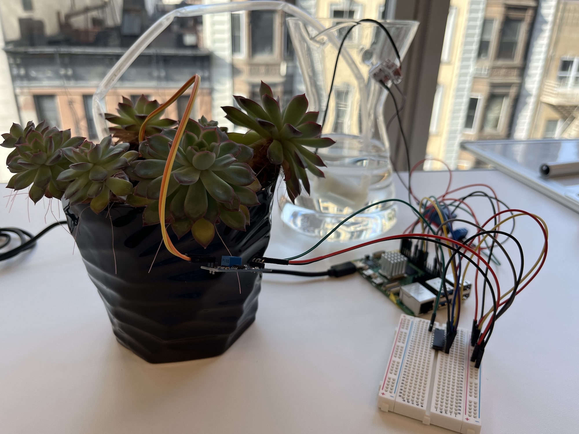
Building a useful machine doesn't have to require complicated code or expensive equipment.
With a Raspberry Pi and some basic hardware, you can keep your plants healthy and happy from anywhere in the world!
Follow this tutorial to learn how to set up an automatic plant watering system:
1. [Complete the physical assembly and wiring](#set-up-your-plant-watering-robot).
1. [Create and connect to the machine, and configure your machine's components](#configure-the-components-of-your-robot).
1. [Configure the ADC as a module from the registry](#configure-the-adc-as-a-module-from-the-registry).
1. [Write code utilizing the Viam Python SDK to control the plant watering robot](#add-python-control-code).
You can also follow a simplified version of this tutorial in this video: it eliminates the need for the ADC and the breadboard, instead using the digital pin of the moisture sensor to get “high” and “low” readings and to turn a relay on and off.
You can start with this simple version and then add the ADC to make your machine more accurate!
The tutorial uses the following hardware, but you can adjust it as needed:
- A Raspberry Pi 3 or later or Raspberry Pi 2 W, including an SD card and [power supply](https://www.amazon.com/CanaKit-Raspberry-Supply-Adapter-Listed/dp/B00MARDJZ4)
- A [resistive soil moisture sensor](https://www.amazon.com/KeeYees-Sensitivity-Moisture-Watering-Manager/dp/B07QXZC8TQ)
- A [5V mini water pump](https://www.amazon.com/gp/product/B09TGK9N5Q/) with clear vinyl tube
- A [MCP3008 ADC](https://a.co/d/csRaIHE)
- A [one channel relay switch](https://www.amazon.com/HiLetgo-Channel-optocoupler-Support-Trigger/dp/B00LW15A4W/)
- A [breadboard](https://www.amazon.com/SunFounder-Raspberry-Breadboard-solderless-Circuit/dp/B07ZYR7R8X)
- Assorted [jumper wires](https://www.amazon.com/EDGELEC-Breadboard-Optional-Assorted-Multicolored/dp/B07GD2BWPY/), including two [splicing connectors](https://www.amazon.com/Splicing-Connector-Lever-Nut-Assortment-Pocket/dp/B07NKSHVF6)
- A planter box or flower pot
- A water container
- A screwdriver
Before starting this tutorial, follow the [Raspberry Pi Setup Guide](/reference/device-setup/rpi-setup/) to prepare your machine to run `viam-server`.
Your Pi must run a Viam-compatible operating system, and you must have SSH access.
## Set up your plant watering robot
Before programming the machine, you need to physically set up the plant watering robot by wiring the different components together.
You will set up the robot to receive signals from the resistive soil moisture sensor and signal to the peristaltic pump when it is time to pump water from the water container to the plant container.
### Full wiring diagram
Refer back to this diagram as you complete the steps to wire your hardware.
Disconnect your Pi from power while you wire.
### Wire your ADC
The analog-to-digital converter (ADC) converts the resistive soil moisture sensor's analog readings to digital signals that can be processed by your machine through GPIO pins.
Start by wiring your ADC to your machine.
Reference the following pinout diagram for your MCP3008 analog-to-digital converter:
> **Tip:**
>
> The half circle shown in the pinout diagram above should be physically present on your ADC.
> Use this to orient the ADC to determine the location to insert your wires.
Insert the MCP3008 into your breadboard so that it bridges both sides of the center divider.
Now you can use the breadboard points next to the MCP3008 to connect pins on the MCP3008 to your Raspberry Pi and other peripherals using jumper wires.
Begin by connecting MCP3008 pins to the following physical pins on the Raspberry Pi:
| MCP3008 ADC Pin | Raspberry Pi Physical Pin | GPIO | Function |
| --------------- | ------------------------- | ---- | -------- |
| DIN | 19 | 10 | MOSI |
| DOUT | 21 | 9 | MISO |
| CLK | 23 | 11 | SCLK |
| CS/SHDN | 24 | 8 | SPI0 |
> **Tip:**
>
> Raspberry Pis use two distinct pin numbering systems:
>
>
>
**Physical pin numbers** correspond to physical positions on the header. Count from left to right, starting at the top-left corner when the Raspberry Pi is positioned with its Ethernet port facing downward.
>
**GPIO numbers** refer to GPIO channel designations used in programming. For GPIO pin assignments, see the Raspberry Pi pinout diagram at [pinout.xyz](https://pinout.xyz).
>
Next, connect the following MCP3008 pins to any point on the indicated rails on the breadboard:
| MCP3008 ADC Pin | Breadboard rail |
| --------------- | --------------------- |
| VDD | 5V power rail (red +) |
| VREF | 5V power rail (red +) |
| AGND | ground (blue -) |
| DGND | ground (blue -) |
Finally, connect your breadboard rails to 5V power and ground on the Raspberry Pi:
| Breadboard rail | Raspberry Pi Physical Pin | Function |
| ---------------------------------- | ------------------------- | ---------------------------------------------- |
| Any point on 5V power rail (red +) | 4 | [5V power](https://pinout.xyz/pinout/5v_power) |
| Any point on GND rail (blue -) | 34 | [ground](https://pinout.xyz/pinout/ground) |
### Wire your resistive soil moisture sensor
Next, wire your [resistive soil moisture sensor](https://www.amazon.com/KeeYees-Sensitivity-Moisture-Watering-Manager/dp/B07QXZC8TQ) to your Pi and ADC.
Reference this diagram of the blue module part of the sensor:
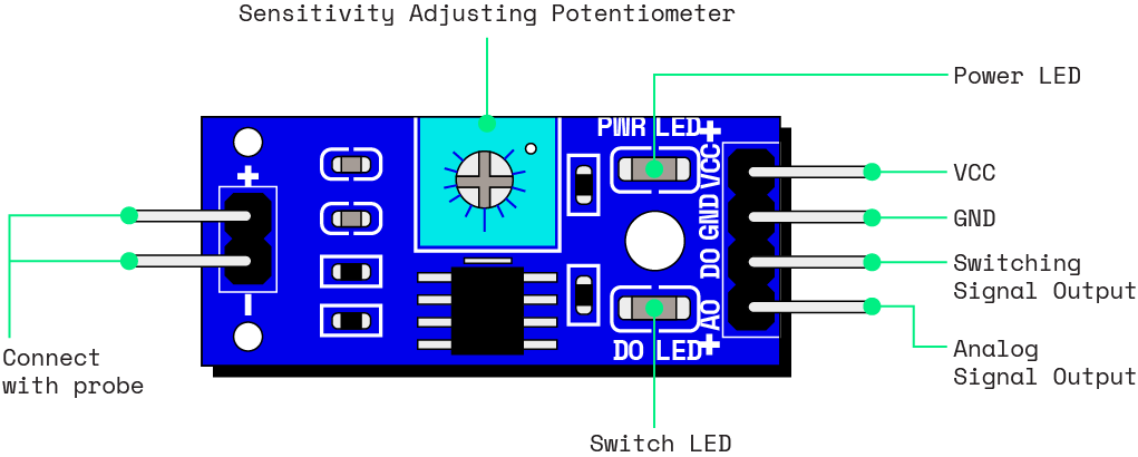
Start by connecting the female jumper wires at the end of the sensor prongs to the blue module where the diagram shown above is labeled "Connect with Probe."
You can connect either wire to either pin on the blue module.
Then, wire the rest of the pins on the module to any point on the indicated row or rails of the breadboard:
| Moisture Sensor Pin | Breadboard points |
| ------------------------- | ------------------------ |
| A0 (Analog Signal Output) | row adjacent to CH0 |
| VCC | 5V power rail (red +) |
| GND | ground rail (blue -) |
Put the soil moisture sensor inside of the container holding your plant.
### Wire your pump
Now, wire and power your pump and relay module to complete your hardware setup.
> **Tip:**
>
> To connect jumper wires to the relay module:
>
>
>
Use a screwdriver to loosen the screws on top of the pin gates on the relay module.
>
Insert a jumper wire pin into the pin gate.
>
Tighten the screws on top of the pin gates to fasten the jumper wires.
>
Connect the pump wires to the following physical pins on the relay and Raspberry Pi:
| Pump Wire | Pin |
| --------- | --------------------------------------------------------------------- |
| positive | Relay module NO |
| negative | Raspberry Pi [pin 39 (ground)](https://pinout.xyz/pinout/ground) |
NO stands for normally open, which will keep the circuit open unless the pin is triggered.
Connect the relay module pins to the following physical pins on the Raspberry Pi:
| Relay Pin | Raspberry Pi Physical Pin | Function |
| --------------- | ------------------------- | ------------------------------------------------- |
| COM | 2 | [5V power](https://pinout.xyz/pinout/5v_power) |
| DC+ | 1 | [3.3V power](https://pinout.xyz/pinout/3v3_power) |
| DC- | 14 | [GND](https://pinout.xyz/pinout/ground) |
| IN | 8 | [GPIO 14](https://pinout.xyz/pinout/pin8_gpio14) |
## Program your plant watering machine
Now that your machine is fully wired, it's time to configure the logic with Viam.
### Enable SPI on your machine
Before you begin, ensure that the Serial Peripheral Interface (SPI) is enabled on your machine.
This protocol allows your machine to communicate with the moisture sensor peripheral.
Connect your Raspberry Pi to power.
SSH into your machine and run the following command:
```shell {class="command-line" data-prompt="$"}
sudo raspi-config
```
Once the `raspi-config` interface is open, navigate to **Interface Options**:
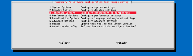
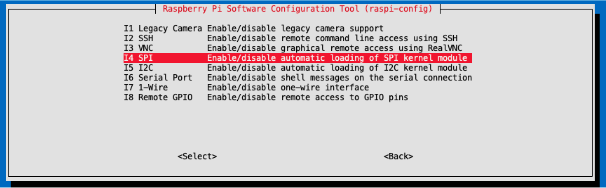
Then, select **SPI**:
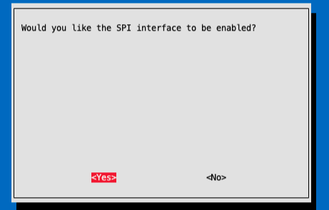
Now, select **Yes** to enable SPI:
Finally, select **Finish**.
Run the following command to reboot your machine and load your changes:
```shell {class="command-line" data-prompt="$"}
sudo reboot
```
### Configure the components of your robot
Add a new machine on [Viam](https://app.viam.com).
On the machine's page, follow the {{< glossary_tooltip term_id="setup" text="setup instructions" >}} to install `viam-server` on the computer you're using for your project.
Wait until your machine has successfully connected to Viam.
Then, navigate to the **CONFIGURE** tab of your new machine's page in the app.
First, add your machine as a [board component](/reference/components/board/):
### Config Builder
Click the **+** icon next to your machine part in the left-hand menu and select **Blocks**.
Search for `raspberry pi`, then select the block that matches your Pi (for example, `raspberry-pi/rpi4` for a Raspberry Pi 4).
Enter a name for your board and click **Add to machine**.
This tutorial uses the name `local`.
### JSON
```json
{
"components": [
{
"name": "local",
"model": "pi",
"api": "rdk:component:board",
"attributes": {},
"depends_on": []
}
]
}
```
#### Configure the ADC as a module from the registry
_Resources_ refer to the different [components](/reference/glossary/#term-component)
and [services](/reference/glossary/#term-service)
Viam provides for robots to use.
_Components_ refer to types of hardware, and each component's built-in `models` support the most common models of this hardware.
For example, the [sensor component](/reference/components/sensor/) has an `ultrasonic` model built in for the ubiquitous [ultrasonic sensor](https://www.sparkfun.com/products/15569).
However, there are many different types of sensors used for sensing different things across the [Internet of Things](https://medium.com/@siddharth.parakh/the-complete-list-of-types-of-sensors-used-in-iot-63b4003ab6b3).
Although the resistive soil moisture sensor is not currently one of Viam's built-in models, you can add an analog-to-digital-converter (ADC) as a module and use it to get readings from the moisture sensor.
A _module_ provides one or more [modular resources](/reference/glossary/#term-modular-resource)
, which add resource types ([components](/reference/glossary/#term-component)
and [services](/reference/glossary/#term-service)
) or models that are not built into Viam.
A module can be added to your machine from the Viam Registry.
The [registry](https://app.viam.com/registry) allows hardware and software engineers to collaborate on their projects by writing and sharing custom modules with each other.
You can add a module from the Viam Registry directly from your machine's **CONFIGURE** tab, using the **+** (Create) button.
To add the [mcp300x-adc-sensor](https://github.com/viam-labs/mcp300x-adc-sensor) module to your machine, follow these steps:
1. Go to your machine's **CONFIGURE** tab.
Click the **+** icon next to your machine part in the left-hand menu and select **Blocks**.
1. Search for `mcp300x` and select `sensor / mcp300x`.
Click **Add module**.
1. Give your module a name of your choice. We used the name `sensor`.
1. Click **Create** to add this module to your machine.
1. Find your module's card on the **CONFIGURE** page.
Copy the following JSON object into the configuration field.
```json
{
"channel_map": {
"moisture": 0
},
"sensor_pin": 8
}
```
`sensor_pin` is the GPIO pin number of the machine's pin you connected to the MCP300x chip: in this case, GPIO `8`.
Save your config by clicking **Save** in the top right corner of the page.
On the sensor configuration panel, click on the **TEST** area to confirm you can get readings from your sensor.
This module allows you to get multiple readings at the same time from different channels of the ADC sensor.
Now that you have set up your machine, place your pump in the water cup, and the output tube in your plant pot!
### Install the Python SDK
Make sure any packages on your Pi are up to date, while connected to your Pi with SSH run:
```shell {class="command-line" data-prompt="$"}
sudo apt update
sudo apt upgrade
```
Make sure you have `pip` installed for Python 3:
```shell {class="command-line" data-prompt="$"}
pip --version
```
If not, run the following command:
```shell {class="command-line" data-prompt="$"}
sudo apt install python3-pip
```
After that, follow [Install the Python SDK](/reference/sdks/python/python-venv/) to create and activate a virtual environment and install `viam-sdk` on your Pi.
### Add Python control code
Follow these instructions to start working on your Python control code:
1. Navigate to your machine's page and click on the **CONNECT** tab.
1. Select **API keys** and copy your **API key**, **API key ID**, and **machine address**.
1. Install the Python SDK and create a connection script using your credentials.
To show your machine's API key in the sample code, toggle **Include API key**.
{{< alert title="Caution: Keep your API key safe" color="caution" >}}
We strongly recommend that you add your API key as an environment variable.
Anyone with your API key can access your machine, and the computer running your machine.
{{< /alert >}}
1. Paste this code sample into a new file on your machine.
1. Name the file plant-watering-robot.py, and save it.
Run the following commands on your machine to create and open the file:
```shell {class="command-line" data-prompt="$"}
source .venv/bin/activate
touch plant-watering-robot.py
nano plant-watering-robot.py
```
Now, add code into plant-watering-robot.py to write the logic that defines your plant watering system.
To start, add your system logic code into the `main()` function of the program.
Use the Viam [board](/reference/apis/components/board/) and [sensor](/reference/apis/components/sensor/) API methods to read from the moisture sensor and control the pump's voltage from a GPIO pin.
To access components from the machine, use the following code snippet:
```python
# Note that this name, `sensor`, is defined when you add the mcp300x module
sensor = Sensor.from_robot(robot=robot, name='sensor')
# Note that this name, `local`, is defined when you add the board
local = Board.from_robot(machine, "local")
```
Then, add a control loop that runs continuously, similar to the following example:
```python
# this level depends on your specific setup, replace after testing
DRY = 600
# amount of time to pump water to plant, in seconds; depends on planter size
WATERING_TIME = 15
# time between moisture checks, in seconds
MOISTURE_CHECK_INTERVAL = 60
# delay after watering before we check moisture level again, in seconds
SOAK_TIME = 600
# GPIO number of pin that toggles the relay
MOTOR_CONTROL_GPIO = "8"
while True:
# Get the moisture sensor's readings
readings = await sensor.get_readings()
soil_moisture = readings.get("moisture")
# If the moisture reading indicates moisture, pump water
if (soil_moisture > DRY):
print("plant is thirsty! watering")
# Get the GPIO pin connected to the IN pin on the relay
motor_control_pin = await local.gpio_pin_by_name(
name=MOTOR_CONTROL_GPIO)
# Run the pump
# Set pin to high to close the relay, connects power to the pump
await motor_control_pin.set(high=True)
# Wait for water to pump
print("it's watering time")
time.sleep(WATERING_TIME)
# Stop the pump
# Set pin to low to open the relay, removes power from the pump
await motor_control_pin.set(high=False)
# Wait an hour to let the soil soak
print("waiting a little bit for the water to soak in")
time.sleep(SOAK_TIME)
# Wait between checks
print("waiting before we test for moisture again")
time.sleep(MOISTURE_CHECK_INTERVAL)
```
> **Tip:**
>
> You must import `time` at the top of plant-watering-robot.py to be able to use `sleep()`!
### Test motor
On your machine's **CONTROL** page, expand the **TEST** panel for your board component. You should see a panel that allows you to control individual GPIO pins:
In the **Pin** field, enter `8` to write to physical pin 8.
To activate the motor and begin pumping water, use the **State** control to select **High**, then click **Set**.
You should hear your motor activate and it should begin pumping water if immersed.
To turn off the motor and stop pumping water, use the **State** control to select **Low**, then click **Set**.
### Test moisture sensor
On your machine's **CONTROL** page, expand the **TEST** card for your `mcp300x` sensor module to see a live observed value from your moisture sensor.
Test your sensor by putting it in air, water, and soils containing different amounts of moisture.
Use these values to determine an appropriate value for the `DRY` variable in your setup.
### Save control code
Save plant-watering-robot.py with this logic added in, and then run it on your machine with the following command:
```shell {class="command-line" data-prompt="$"}
sudo python3 plant-watering-robot.py
```
## Next steps
Now that you have created your automatic plant watering system with a resistive soil moisture sensor, you can easily use Viam to automate other aspects of your garden.
For example, you could add a [light sensor](https://www.amazon.com/Sensor-Module-Raspberry-Integrated-Circuits/dp/B07L15M5JG) or a [temperature sensor](https://www.amazon.com/KY-011-Cathode-Arduino-Starter-2-color/dp/B07869PKKF/ref=as_li_ss_tl?keywords=arduino+two+color+led+module&qid=1556591832&s=gateway&sr=8-2&th=1&linkCode=sl1&tag=murraynet-20&linkId=c36cd98be29498a9883b656c7011b6bb&language=en_US), and get readings from other channels of the MCP3008!
You could set up data capture and [graph your sensor data](/data/visualize-data/), or [create your own custom Typescript dashboard](/tutorials/control/air-quality-fleet/) to display your sensor data.
If you build something based on this please share it in our [Community Discord](https://discord.gg/viam) - we'd love to see it.